Embedded Webcam
Project Duration: January 2020 - March 2020
Team: Joshua Cho, Silvester Jang
Acknowledgements: Dr. Ilya Mikhelson, Roberto Roches
GitHub RepositoryIntroduction
Embedded webcam was a quarter-long project for my elective course, EE326: Electronic System Design I, at Northwestern University. The goal of this project was to build a fully functional embedded webcam from scratch, and stream its images to a website. I decided to take this course because I wanted more experience designing and building an embedded system from start to finish, and also to broaden my knowledge in electrical engineering, as well as software development. Overall, this project gave me a valuable opportunity to prototype an IoT product and bring it to a final form.
Design Process
Component Selection
The design process started with selecting the components for the prototype. The main components that we chose were:
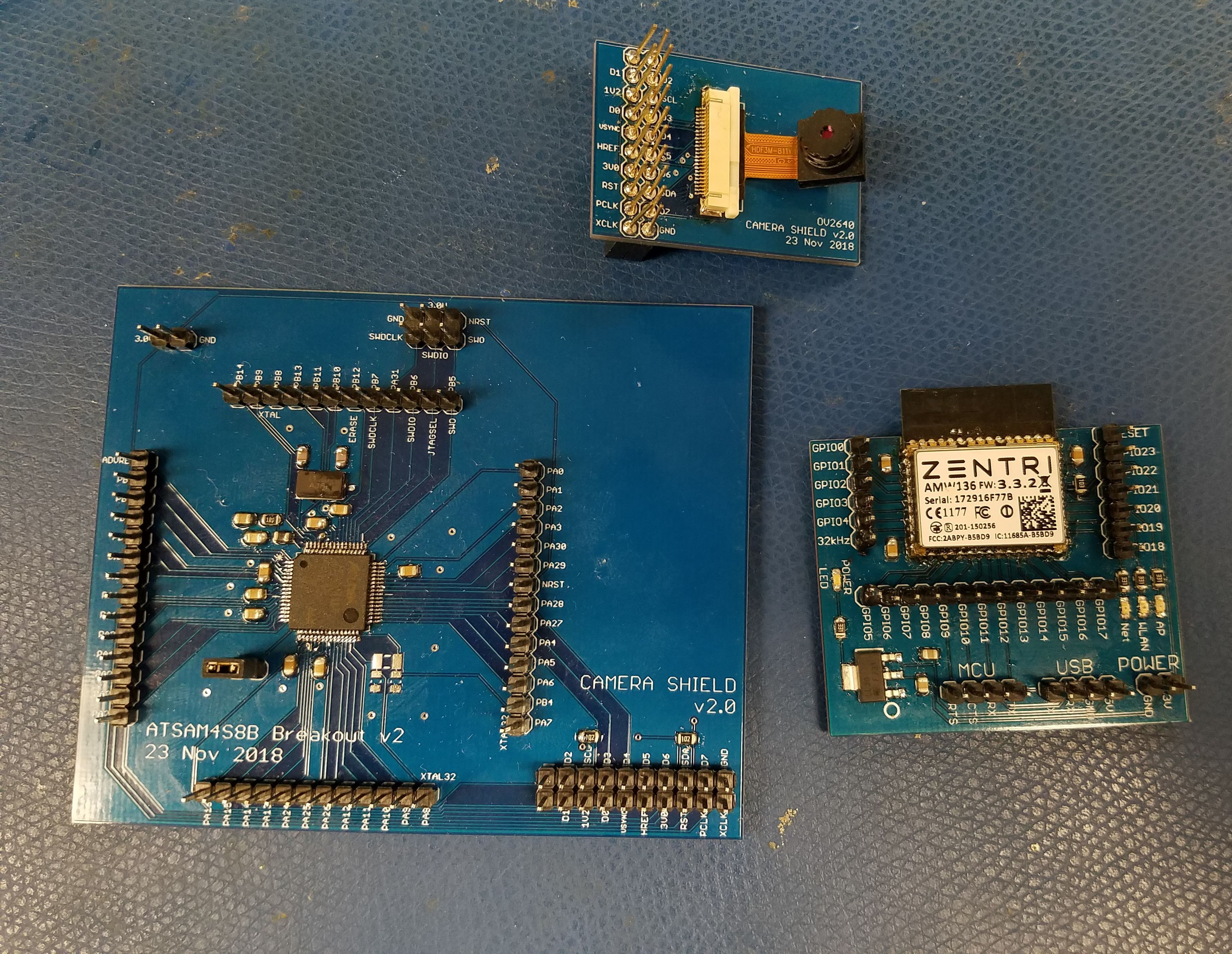
- Microcontroller: Microchip ATSAM4S8B (64-lead LQFP package)
- WiFi module: Zentri AMW136
- Camera module: OV2640
- Voltage regulator: TLV1117LV 1-A (5V to 3V)
The prototype also required standard surface mount capacitors, resistors, LEDs, crystal oscillators, and through-hole pushbuttons. The Zentri AMW136 WiFi module came with ZentriOS, an IoT operating system that supports command API. This allowed the WiFi module to receive commands directly from the MCU or a remote terminal via USART interface. It also came with built-in GPIO pins that can be configured to serve different useful purposes.
With all the components in hand, we were able to solder them onto intermediate breakout boards and test their functionality together before designing a final PCB. We also wrote our firmware at this stage so that we can easily modify connections when necessary.
Firmware Design
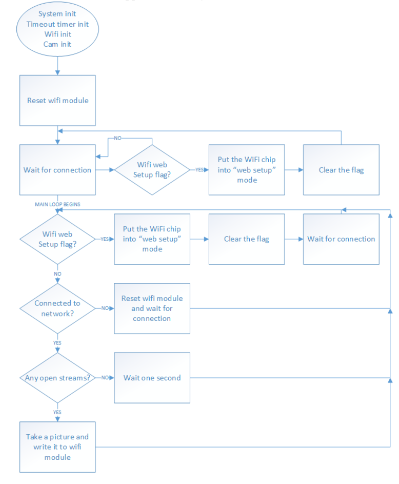
The main function of this webcam was to take pictures and stream them when it detects that a websocket is open. It also needed two pushbuttons: one that resets the system (MCU), and one that puts the WiFi module into "web setup" mode. With these features in mind, we wrote our firmware following the flowchart below:
The firmware was written in C language in Atmel Studio. It involved writing functions that allowed the MCU to send commands to the WiFi module via USART, and receive and process the responses. We also configured interrupt requests and handlers to listen to the web setup button press and the "command complete" signal from the WiFi module.
In our main function, first, we ran all initializations. Then, we looped through a set of commands. More specifically:
- Initialization
- Initialize clock and board definitions.
- Configure and start the Timer.
- Configure the WiFi USART, as well as the Command pin and Web Setup pin.
- Reset the WiFi and wait for it to connect to a network. While waiting, listen for the Web Setup pin.
- Initialize and configure the camera.
- Tell the WiFi to turn off the command prompt and command echo.
- Loop
- Check for Web Setup request.
- If network is available, query available websocket connections. If it is not, reset the module.
- If no connections available, delay 1s and start over.
- If connections available, take picture.
- If picture taken successfully, transfer it to the AMW136.
We spent the majority of our time in this project completing the firmware as it was very difficult to debug errors in our code, especially when they were occurring at a register level. Nevertheless, we utilized debugging tools like Logic Analyzer, Tera Term, the built-in debugger in Atmel Studio, and the datasheet to finish our firmware.
PCB Design
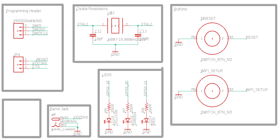
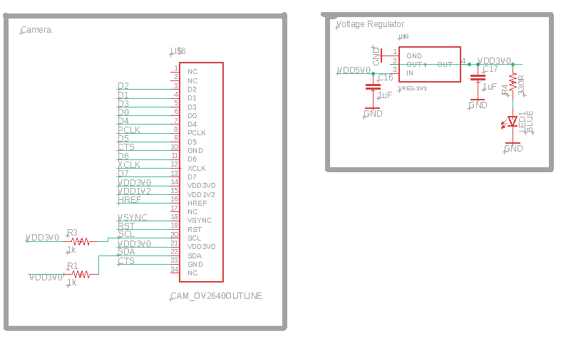
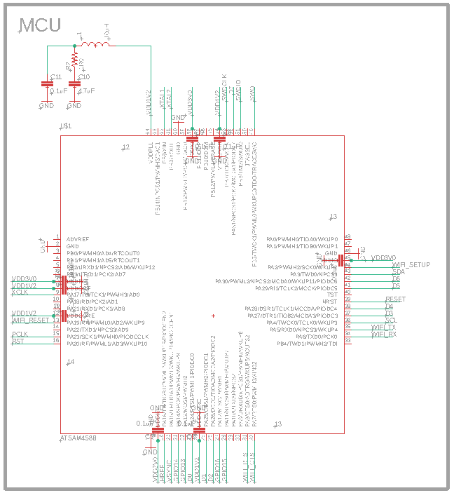
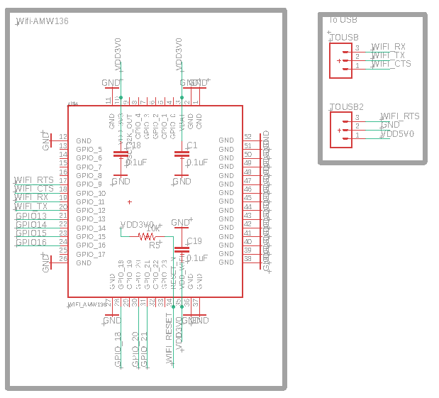
After we finalized and tested our firmware on the breakout boards, we designed a custom PCB in EAGLE to integrate all components and connections. We included a 5V barrel jack to power the board, and some programming and USB headers. The final layout of the board is shown below.
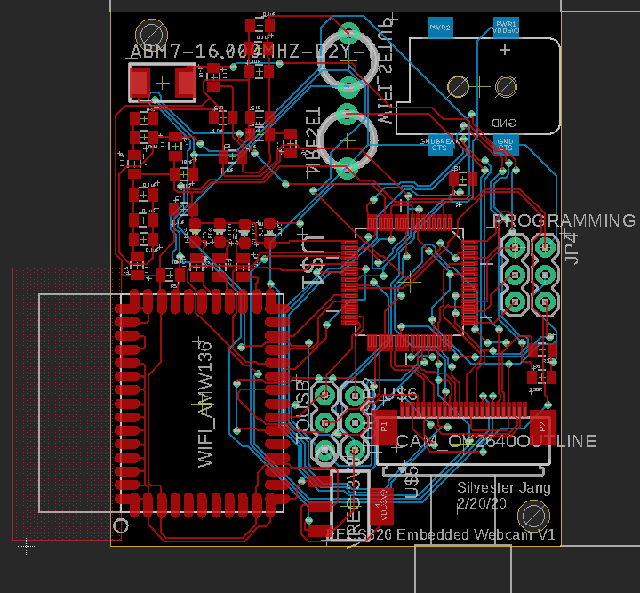
The finished board ended up being 50mm x 48mm in size, and worked perfectly!
Enclosure Design
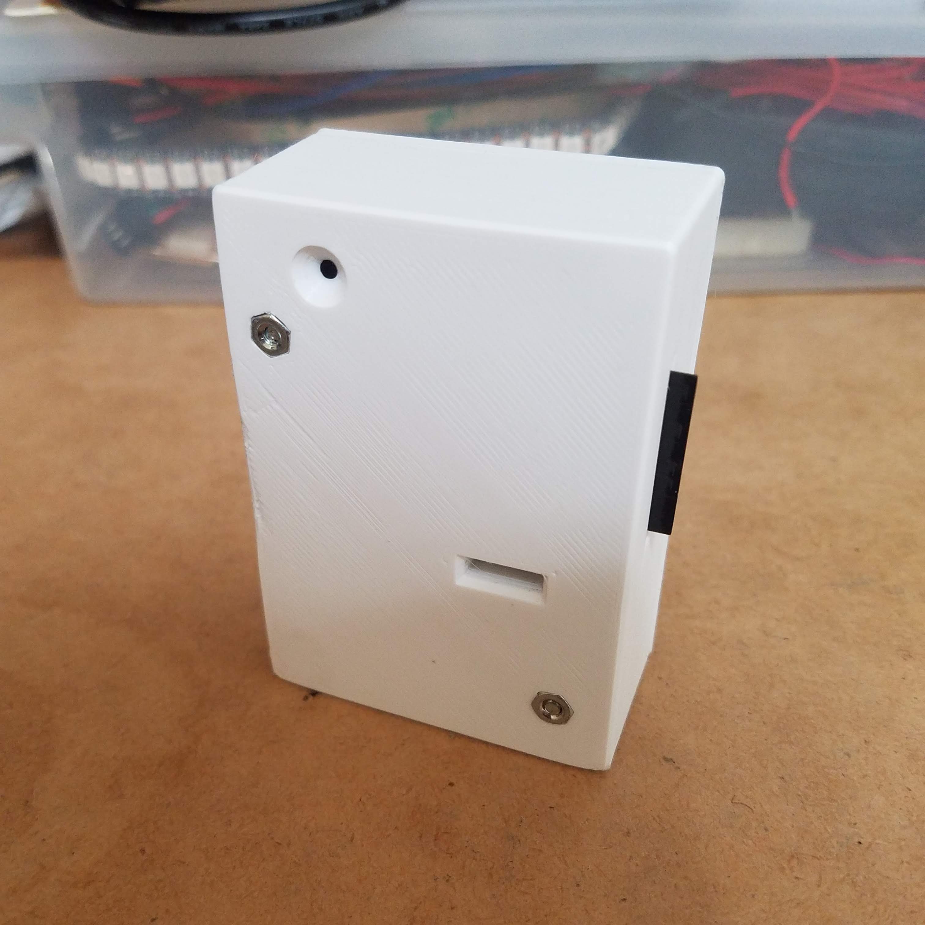
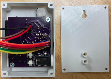
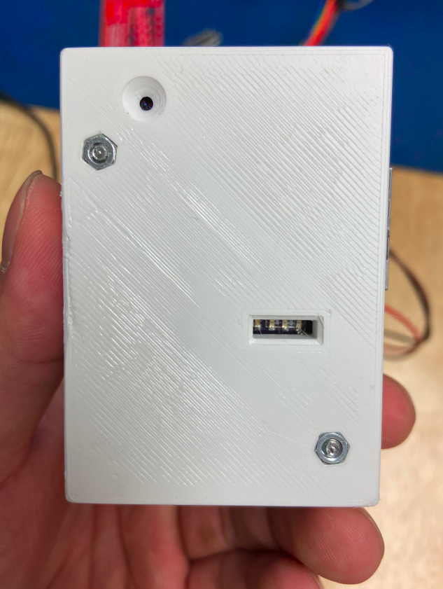
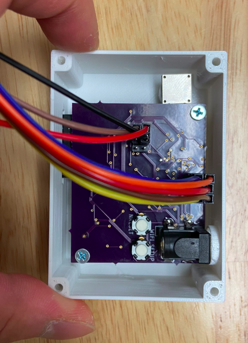
To become a finished product, the PCB need to be mounted inside a custom enclosure. We designed the CAD model
of the enclosure in Onshape.
Some main features included supporting structures for the PCB, cutouts for the WiFi antenna, the camera, LEDs, and the power supply.
We also included small holes for the two buttons. These buttons were meant to be pressed using a narrow pin, just like how they would
on a consumer electronic device.
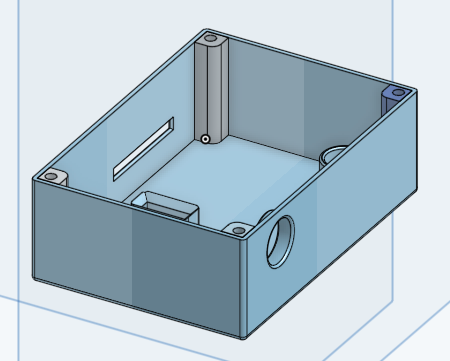
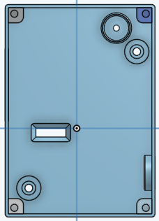
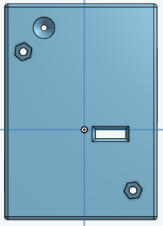
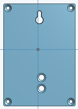
We used Prusa i3 MK3 printer and PLA filament to 3D print our enclosure. It took some trial and error, as well as playing with the settings to get the best print quality and a perfect-fitting enclosure. The PCB, the enclosure, and the lid were all fastened using standard M2.5 screws.
Website
The final part of creating an embedded system was to create a simple website from which we can view the webcam image. The website consisted of three pages: a main homepage, a webcam page that displays the actual webcam image and its timestamp, and an info page that containts a brief description about ourselves.
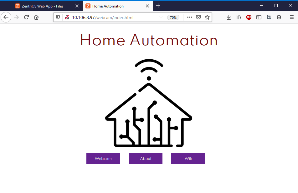
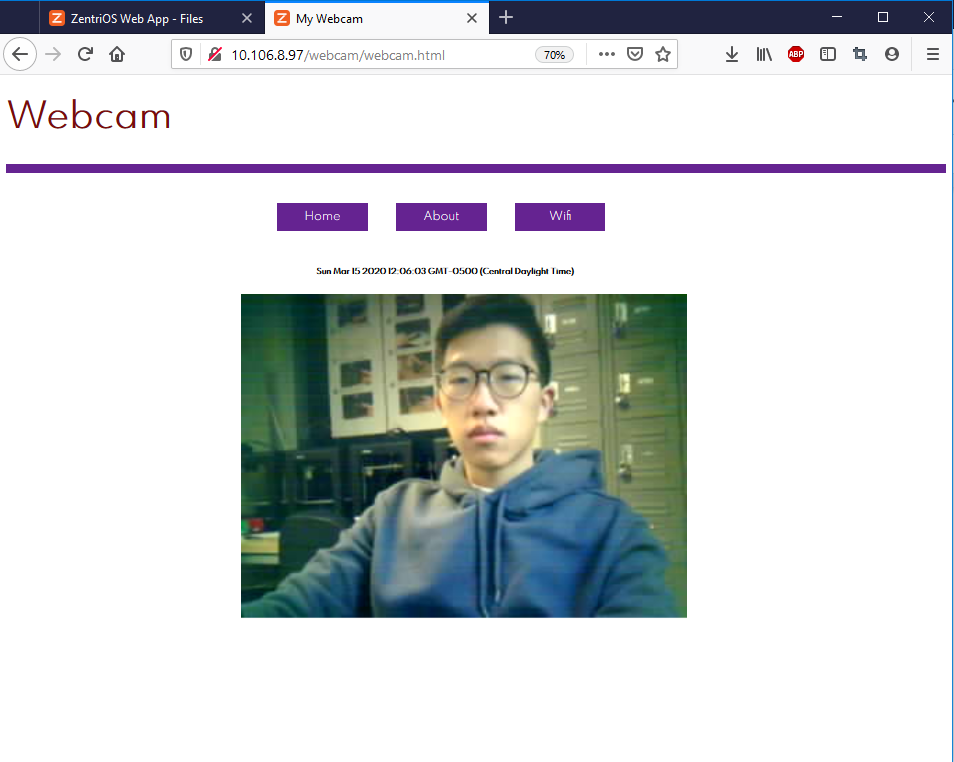
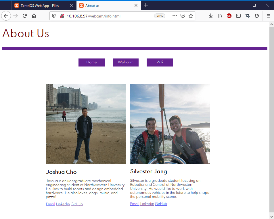
The actual website was crafted using a combination of javascript, html, and css scripts. Javascript functions were heavily used to make sure that the webcam images are being transferred properly with the correct timestamps to the webcam. To make the website look more professional, We also added some button animations, so that the start/stop button appears only when the cursor is hovering over the webcam image. The website was successfully able to capture the webcam image and display it at about 1 frame per second.
Demo
Future Development
- Reduce the size of the PCB by utilizing both sides of the PCB and placing the bypass capacitors closer to the MCU
- Increase frame rate by maximizing the system clock speeds and lowering the resolution
- Improve the camera enclosure for better tension relief
- Redesign the website using a professional framework
Conclusion
In this course I learned how to create an embedded system from scratch through building a fully integrated webcam, including the hardware, the firmware, and a website. Seeing our group’s finished product that worked perfectly after ten weeks of hard work was very rewarding. Throughout this course, I learned many new skills like surface mount soldering and web development, while also brushing up and improving my skills like coding in C, designing PCBs in EAGLE, CAD, and 3D printing.