McCormick Robot Design Competition
Project Duration: March 2019 - May 2019
Team: Joshua Cho, Paulina Robles
Acknowledgements: Nick Marchuk
Introduction
For McCormick Robot Design Comptition, my teammate Paulina and I built a bluetooth-controlled gripper robot that can navigate around obstacles and move rectangular objects. It has multiple sensors that allow it to scan its surroundings and stream the information to a graphical display. Our robot was the recipient of the Myke Minbiole Elegant Engineering Award.
McCormick Robot Design Competition is an annual tournament-style competition held within Northwestern's McCormick School of Engineering.
Each year, teams are challenged to build an autonomous or a semi-autonomous robot to complete a series of tasks.
This year's tournament was based on the famous board game Battleship.
The playing field consists of two 6ft by 6ft square boards, separated by a barrier that prevents the teams from
seeing the other side. Teams place their robots on the opposite board, and then place four rectangular tokens and walls on their own board.
Then, teams must only use the sensor data from their robots to remotely control them and push all of the opponents' tokens off their board.
The team that removes all tokens first wins the round. No cameras are allowed.
Mechanical Design
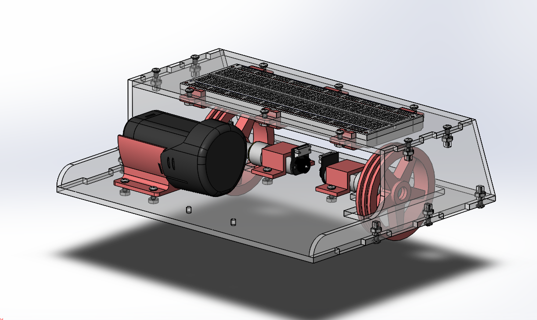
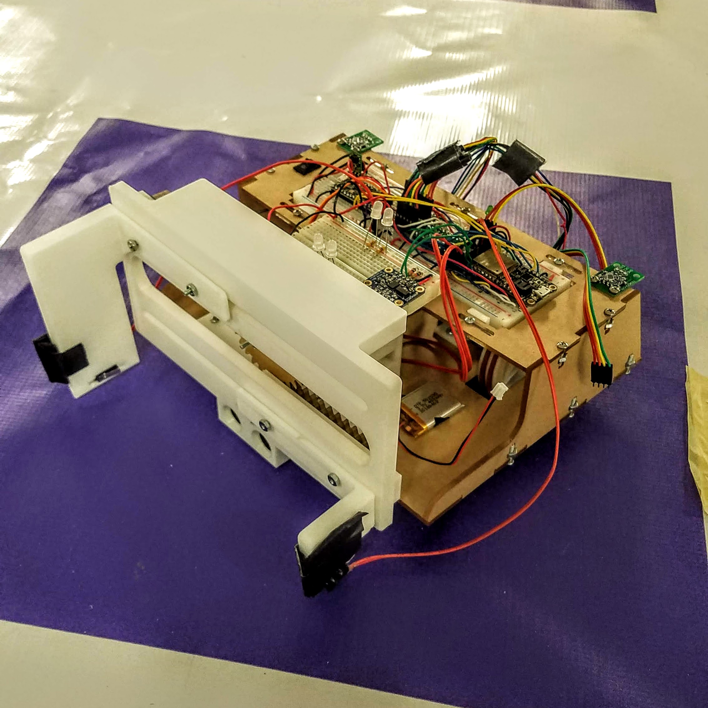
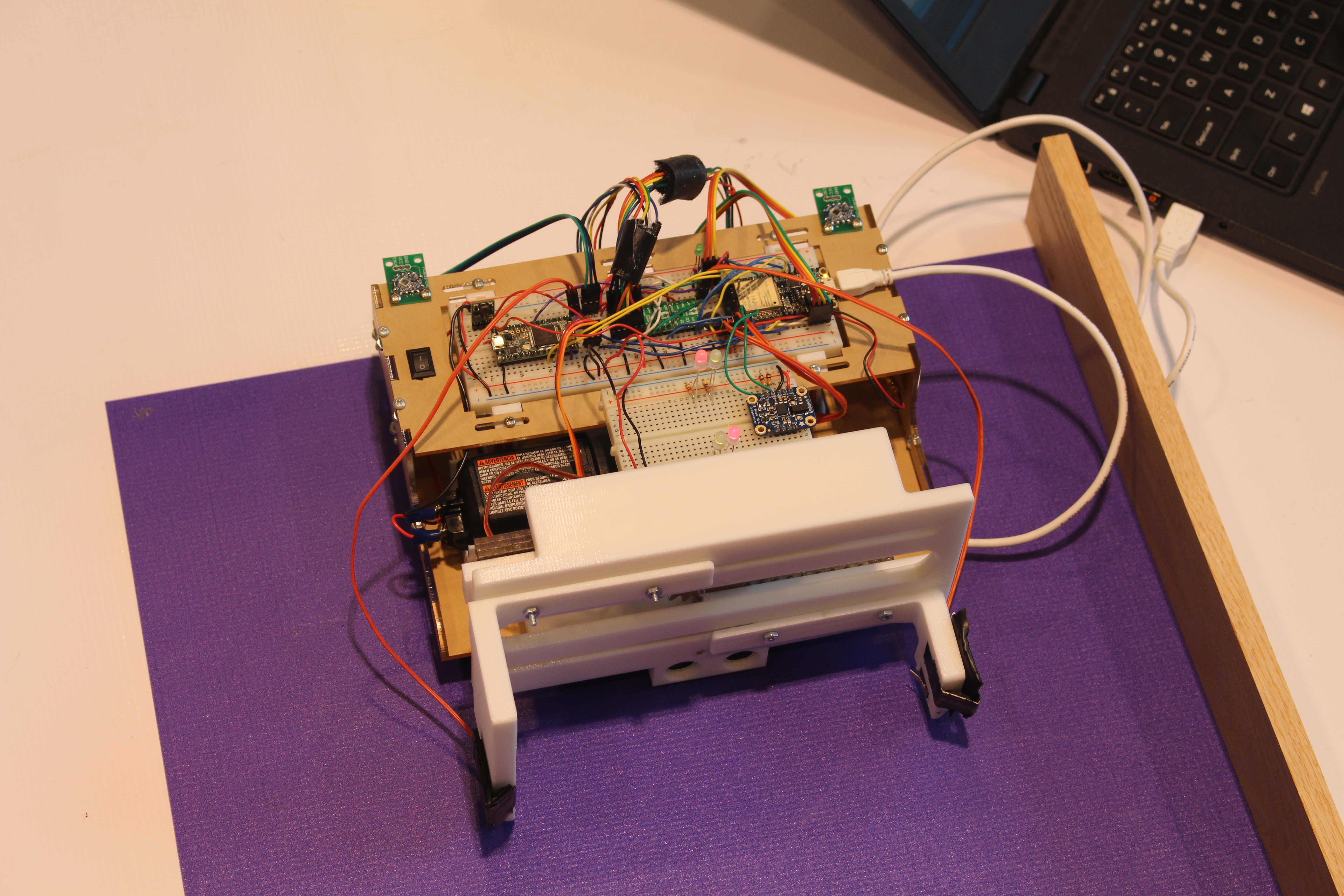
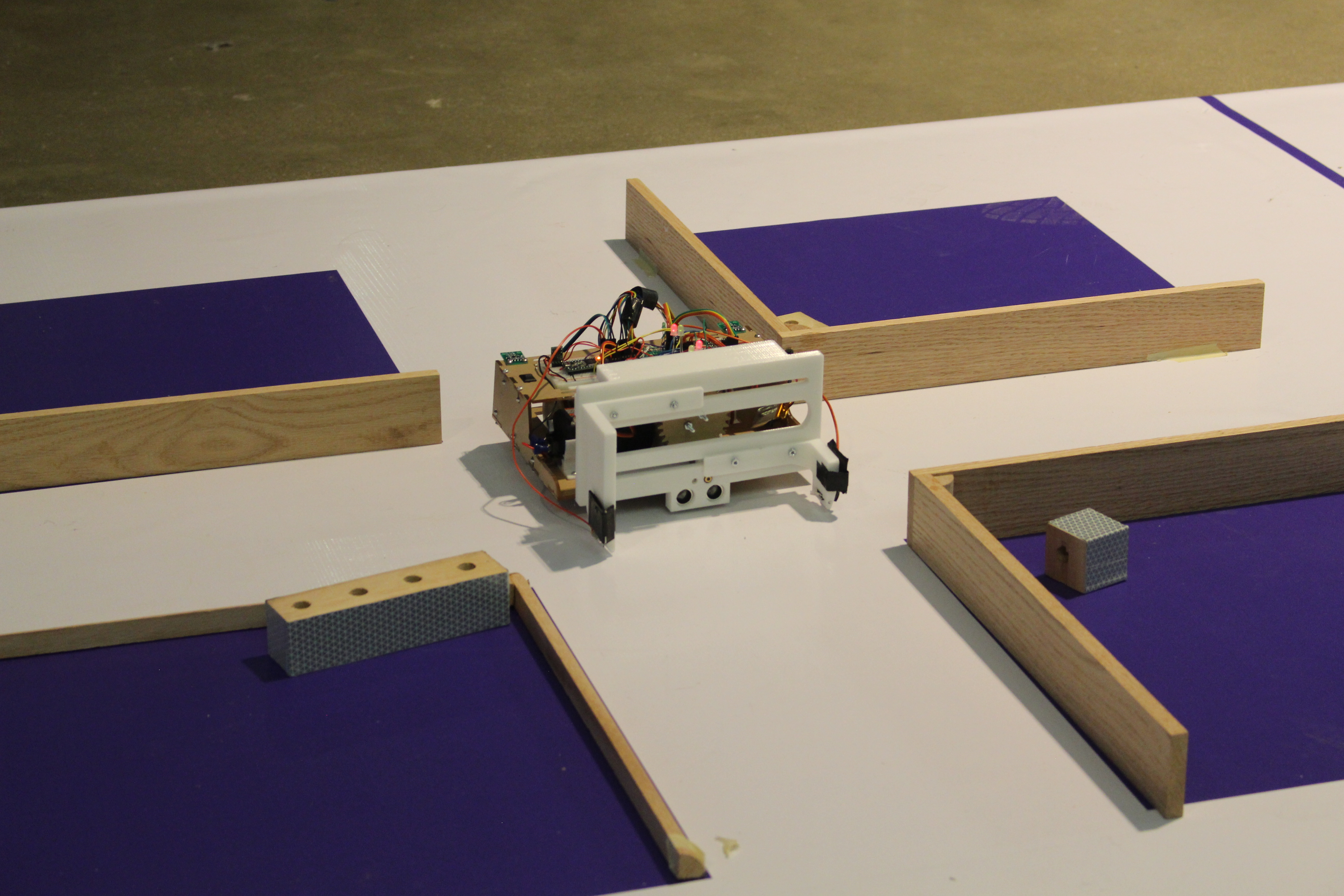
The frame of the robot was built from laser cut 1/8" thick acrylic held together using a combination of puzzle and t-slot joints. The bottom layer held two motors and the battery, as well as the gripper module. The motors and the battery were secured using 3D-printed mounts. The wheels were also 3D-printed and had grooves to put O-rings around for traction. The top layer held the breadboard that contained all necessary electronics.
The robot utilized rack-and-pinion style grippers controlled by a single servo in the center. The grippers and the base plate that held the grippers were 3D printed, while the gears were made from laser cut acrylic. The grippers extended linearly up to 6.5 inches wide and could grab tokens of all sizes. Limit switches were embedded in the grippers to let the driver know when it had a firm grip on a token.
Electronics
The robot used ESP32 Feather HUZZAH32 for most of its operations and bluetooth capabilities. The robot was powered by a 12V Bosch drill battery, and a 3.7V Lipoly battery for the Feather. For the drivetrain, it used two Chihai 12V DC motors with rotary enconders, which were controlled by MAX14870 motor drivers from Pololu.
In order to locate the tokens, our robot utilized several sensors. We used two HTC Vive sensors on each side of the robot paired with a Teensy 3.2 to obtain the x and y positions of the robot on the map. The data was then communicated to the Feather via UART. We later discovered that the coordinates received from the Vive sensors were distorted, and that they did not translate very well to the real life coordinates of the playing field. We got around this issue by collecting Vive coordinate points at 5 different locations on the playing field before every match, then performing a linear transformation to match the actual coordinates. Consequently, we decided to use a BNO055 absolute orientation sensor from Adafruit for orientation instead of trying to do the math with unreliable Vive data.
A laser and a phototransistor were paired together to detect the tokens, which had retroreflective surfaces. This was done by flashing the laser at 20Hz, then measuring how much reflected light was captured by the phototransistor. By setting a threshold for the difference between the phototransistor readings when the laser was off and when the laser was on, we could effectively tell whether the robot was in front of a token or a wall.
Lastly, we used a HC-SR04 ultrasonic distance sensor to measure the distance between the robot and the object in front of it with the accuracy of +/- 3mm. Knowing the position and the orientation of the robot, and the distance between the robot and the tokens and walls, we were finally able to obtain the precise absolute positions of the game elements.
GUI/Control
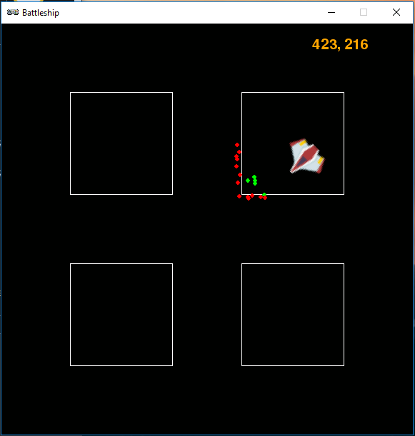
The data obtained from the sensors were transmitted to my laptop via bluetooth, which parsed and displayed them in a PyGame Zero window. The graphical display gave us a visual representation of the playing field and the game elements. The position and the orientation of the robot was represented by the spaceship icon. The map was then populated with green and red dots as the robot began navigating and scanning its surroundings. A green dot was placed where the robot detected an object with a reflective surface (token), and a red dot was placed where the robot detected an object with a non-reflective surface (wall).
The robot was controlled by holding down WASD keys on the laptop keyboard. We also added functions to make the robot move by a set angle/distance increment by lightly tapping on the keys instead of holding. This allowed the robot to make more precise movements when trying to grab the tokens. All maneuvering was done by PID control.
Demo
Conclusion
The mechanical component of our robot was very successful and we ended up winning the Myke Minbiole Elegant Engineering Award. The grippers worked perfectly and had no problem grabbing the tokens regardless of size or position. However, we did have some issues with our software. The Vive readings were distorted and noisy, so even with a linear fit, we experienced error in locating our robot. Incremental turning was also not a good idea; although the robot was able to make precise turns, it turned very slowy especially with the inherent latecy that came with bluetooth.